

Glass-Lined Paddle Agitator
The paddle agitator is suitable for glass-lined reactors with capacities from 50l to 32000l. It is a versatile mixing solution for processes that require stronger axial circulation, balanced mixing performance, and good adaptability across different operating conditions. The paddle agitator is widely used in glass-lined reactors and is especially suitable for applications where stable circulation and broad process compatibility are important.
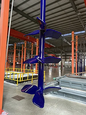
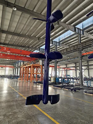
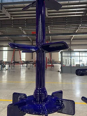
The paddle agitator combines a bottom impeller with multiple pitched blades to strengthen axial flow inside the reactor. This design helps move liquid downward, drive circulation along the vessel wall, and return the material upward to form a stable flow pattern. The paddle agitator is one of the most widely used agitator options for closed-type glass-lined reactors and can be used together with a baffle-type thermowell to further improve axial mixing performance.
- Combined blade design for stronger circulation
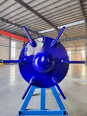
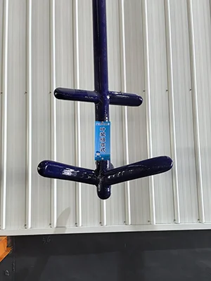
The paddle agitator typically uses a three-blade backward-curved impeller at the bottom and can be configured with one to three layers of pitched blades above it. This structure helps balance discharge performance and overall circulation inside the reactor. - Stable axial flow pattern
The pitched blades push the liquid downward, while the bottom impeller throws the material toward the vessel wall and drives it upward again. This flow pattern helps create stable axial circulation throughout the reactor. - Widely adaptable for different process duties
The paddle agitator is a general-purpose agitator solution with strong adaptability, making it suitable for a wide range of mixing requirements in glass-lined reactors. - Structure suitable for glass lining quality control
The paddle agitator uses a flattened round-tube formed structure, which helps reduce stress concentration and supports better control of glass lining quality during manufacturing. - Reliable shaft and blade materials
The agitator shaft uses export-grade seamless steel pipe, which helps improve lining stability and consistency. The pipe ends use a closed-end head structure, which helps reduce stress concentration caused by thermal necking processes and lowers the risk of enamel chipping.
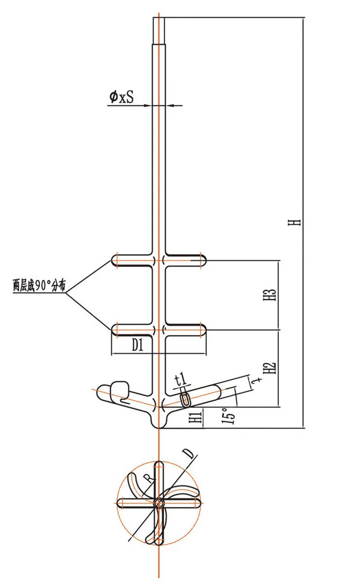
| Size | Main Dimensions (mm) | ||||||
| ∅×S | H | H1 | H2 | H3 | D | D1 | |
| 80*8 | 1760 | 120 | 450 | - | 700 | 650 | |
| 80*8 | 2170 | 135 | 450 | - | 700 | 650 | |
| 80*8 | 2430 | 135 | 450 | - | 700 | 650 | |
| 95*8 | 2620 | 135 | 550 | - | 700 | 650 | |
| 95*10 | 3500 | 135 | 600 | - | 700 | 650 | |
| 95*10 | 3850 | 135 | 650 | 650 | 700 | 650 | |
| 110*12 | 3940 | 135 | 650 | 650 | 900 | 750 | |
| 110*12 | 4120 | 135 | 650 | 650 | 900 | 750 | |
| 110*12 | 4620 | 150 | 650 | 800 | 900 | 750 | |
| 140*14 | 5560 | 150 | 800 | 1000 | 1000 | 850 | |
| 140*14 | 5870 | 150 | 1000 | 1000 | 1000 | 850 | |
| 160*14 | 6800 | 150 | 1000 | 1000 | 1200 | 1000 | |
| For shaft-end dimensions, see the agitator stand shaft-end drawing. | |||||||